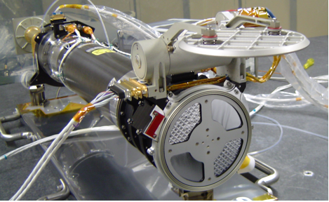
The EUVI telescope was developed at (LMSAL). The EUVI mirrors were figured and coated at (IOTA) and calibrated at (IAS), the focal plane assembly was developed at NRL and the University of Birmingham, the camera electronics were developed at RAL, and the aperture door was supplied by (MPS). The EUVI observes the chromosphere and low corona in four different EUV emission lines between 17.1 and 30.4 nm. It is a small, normal-incidence telescope with thin metal filters, multilayer coated mirrors, and a back- thinned CCD detector. Figure 2-1 shows one of the EUVIs during integration at LMSAL. Figure 2-2 is a cross section through the telescope.
Figure 2-1 The EUVI telescope prior to integration into the SECCHI suite. The door is open and reveals the thin Al entrance filters. The bottom left and top right filters are mesh based filters, the others are polyimide backed supported on a coarse grid
EUV radiation enters the telescope through a thin metal film filter of 150 nm of aluminum. This filter suppresses most of the UV, visible, and IR radiation and keeps the solar heat out of the telescope. During launch, the filter is protected by the front door. The radiation then passes through the quadrant selector to one of the four quadrants of the optics. Each quadrant of the primary and secondary mirror is coated with a narrow-band, multilayer reflective coating, optimized for one of four EUV lines. After bouncing off the primary and secondary mirror, the radiation continues through a filter wheel that has redundant thin-film aluminum filters to remove the remainder of the visible and IR radiation. A rotating blade shutter controls the exposure time. The image is formed on a CCD detector. The main parameters for the EUVI telescope are summarized in Table 2-1.
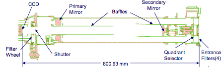
Figure 2-2. EUVI telescope cross section.
Table 2-1. EUVI Telescope Properties
| Instrument Type | Normal incidence EUV telescope (Ritchey-Chrétien) |
| Wavelengths | He II 30.4 nm, Fe IX 17.1 nm, Fe XII 19. 5nm,Fe XV 28.4 nm |
| IR/visible/UV rejection | > 10^13 using thin metal film filters |
| Aperture | 98 mm at primary mirror |
| Effective Focal Length | 1750 mm |
| Field of View | Circular full sun field of view to ±1.7 solar radii |
| Spatial Scale | 1.6" pixels |
| Detector | Backside illuminated CCD (e2v CCD42-40), 2048 x 2048 pixels |
| Mechanisms | Aperture door, Quadrant selector, Filter wheel,Focal plane shutter |
| Image Stabilization | Active secondary mirror (tip/tilt) Range: ±7", jitter attenuation: factor 3 at 10 Hz |
The EUVI telescope is a Ritchey-Chrétien system with a secondary mirror magnification of 2.42. This system provides pixel limited resolution across the entire field of view in all four quadrants. The low secondary mirror magnification reduces the telescope's sensitivity to shifts in the mirror separation and eliminates the need for a focus mechanism. The telescope is fully baffled to prevent charged particles entering the front aperture from reaching the CCD. The telescope pupil is located just in front of the primary mirror and is defined by an aperture mask. The baffles and aperture mask have been designed for an unvignetted field of view to ±1.7 solar radii. Figure 2-3 shows ray trace results for a single quadrant, both on-axis and at the edge of the field, and up to 0.15 mm inside and outside of nominal focus. The system has a minor amount of field curvature; the nominal focus location is chosen to minimize the aberrations across the field.
The EUVI mirrors were figured, polished, and multilayer coated at the Institut d'Optique in Orsay, who also made the mirrors for SOHO/EIT. The Zerodur mirror substrates were first polished to a sphere and superpolished to the required surface roughness. They were then aspherized using an ion beam etching technique that preserves the superpolished properties of the surface. Finally, each quadrant of each mirror was coated with a narrow passband reflective multilayer, optimized for the specific EUV emission to be observed in that quadrant. All coatings consist of MoSi layer pairs. The coating for the 28.4 nm quadrant has a variable layer spacing for optimum suppression of the nearby 30.4 nm He II emission line. The other coatings use constant layer spacings. Table 2-2 summarizes the properties of the coatings (Ravet et al, 2003).
Figure 2-3. Ray trace results for a single quadrant and two field angles (0 and 27 arcmin) at nominal focus, and up to 150 μm inside (-150) and outside (150) of nominal focus. The boxes indicate the size of one CCD pixel.
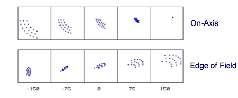
Table 2-2. Properties of the multilayer coatings.
| Quadrant/Channel | 17.1 | 19.5 | 28.4 | 30.4 |
| Center wavelength (two mirror system) | 17.3 nm | 19.6 nm | 28.5 nm | 30.7 nm |
| Bandwidth (measured FWHM for single reflection) | 1.4 nm | 1.6 nm | 1.9 nm | 3.0 nm |
| Peak reflectivity (measured, for single reflection) | 39 % | 35 % | 15 % | 23 % |
| Coating materials | MoSi | MoSi | MoSi, var. spacing | MoSi |
The EUVI uses thin metal film filters at both the entrance aperture and near the focal plane to suppress undesired UV, visible, and IR radiation. Two types of filters are at the entrance of the telescope (Figure 2- 1): an aluminum-on-polyimide foil on a coarse nickel grid for the short wavelength quadrants (17.1 and 19.5 nm), and a single layer aluminum foil on a fine nickel mesh for the long wavelength quadrants (28.4 and 30.4 nm). Both types of filters use a 150 nm thick layer of aluminum to reject visible light. The grid- supported aluminum filter is backed with a 70 nm thick layer of polyimide for strength. The polyimide layer allows the filter to be supported by a coarse grid with 5 mm line spacing that causes only minimal diffraction at EUV wavelengths. The polyimide transmits only about 50% of the EUV radiation at the observing wavelengths, but this is not a major concern for the strong lines at 17.1 and 19.5 nm. The mesh supported filter avoids the absorbing polyimide layer, whose transmission is too low at longer wavelengths, especially for the somewhat weaker line at 28.4 nm. However, the fine mesh, with 0.36 mm line spacing, causes a noticeable amount of diffraction. Both types of filters have been flown on highly successful experiments: EIT used a plastic reinforced aluminum foil on a nearly identical coarse grid for all wavelengths and TRACE (Strong et al, 1994) used fine mesh supported filters nearly identical to the ones on the EUVI. Near the focal plane 150 nm thick aluminum filters on a fine mesh are housed in a filter wheel. The filter wheel offers redundant filters in case pinholes should develop on orbit. A third filter wheel position contains two filters in series to mitigate against any catastrophic damage to the entrance filters. The fourth filter slot is left open, primarily for ground testing. All filters were manufactured by LUXEL Corporation.
The EUVI telescope contains blue and violet light emitting diodes (LEDs) for testing and calibration purposes. One set of LEDs is mounted in the spider and illuminates the detector through reflection off the two telescope mirrors. A second set is mounted near the CCD. Photons from the blue LED at 470 nm have a similar penetration depth in silicon as EUV photons, while photons from the violet LED at 400 nm provide a diagnostic that is sensitive to CCD surface effects. Photons from the violet LED at 400 nm have a shallower penetration depth and may potentially provide a diagnostic for changes in the sensitivity of the surface layer of the CCD.
The EUVI uses a Graphite/Cyanate Ester metering tube as the main telescope structure. The tube stiffness maintains proper alignment of the optical system through launch. The low coefficient of thermal expansion (CTE) in the axial direction minimizes changes in the mirror separation and keeps the telescope in focus throughout the operational temperature range. This eliminates the need for a focus mechanism. The metering tube is lined with an aluminum foil on the inside that acts as a vapor and contamination barrier.
Attached to the front of the metering tube are the secondary mirror spider, the quadrant selector spider, and the entrance chamber with the entrance filters and the interfaces to the aperture door and the forward mount. The spider arms are hollow and incorporate separate vent paths for the secondary mirror tip-tilt mechanism and for the quadrant selector motor. Attached to the aft end of the metering tube are the primary mirror mount and the aft metering structure with the shutter and filter wheel mechanisms, as well as the interfaces to the focal plane assembly and the aft mounts. The aft structure again incorporates separate vent paths for its mechanisms to minimize potential sources of contaminants inside the optical cavity.
The EUVI primary mirror and mount are shown in Figure 2-4. The mount consists of a hexagonal Titanium ring that interfaces to the mirror substrate via three bi-pod flexures. This arrangement is semi-kinematic: each bi-pod strongly constrains two degrees of freedom, but is relatively flexible in the other four, thus isolating the mirror from thermal stresses in the mount. Interferometric tests showed that temperature changes of up to 22 C cause no measurable deformation of the mirror figure. The bi-pods are made of Invar and attach to the Zerodur mirror through bonded Invar mounting pads. This mirror mount is very compact to fit the tight envelope constraints of the EUVI telescope.
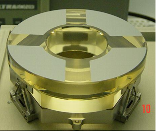
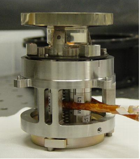
Figure 2-4. Left - EUVI primary mirror, coated and mounted. the mirror diameter is 105 mm. The regions between the quadrants are deliberately left uncoated. Right - EUVI secondary mirror and tip-tilt mechanism. The mirror diameter is 48 mm. One of the three PZTs (marked "L2...M") is clearly visible inside the housing.
The secondary mirror mount with its tip-tilt mechanism is shown in Figure 2-4. The mount is a single piece of Invar with three machined fingers that are bonded to the cylindrical base of the Zerodur mirror substrate. The tip-tilt mechanism is very similar to the one on the TRACE telescope. It uses three piezoelectric (PZT) actuators that push against the Invar mount of the mirror. Software in the SECCHI flight electronics processes fine pointing signals from the SECCHI guide telescope and drives the PZT actuators open loop via a simple digital-to-analog converter and low voltage drivers. The tip-tilt range in the EUVI image space is ±7 arcseconds, sufficient to accommodate worst case spacecraft jitter.
The EUVI focal plane assembly (FPA) houses the e2v CCD42-40 detector and is passively cooled via an aluminum cold finger and a radiator surface at the anti-sun deck of the STEREO spacecraft. The FPA is equipped with a heater to keep the CCD warm during the time of high outgassing rates shortly after launch, and for occasional warmups for decontamination purposes and for annealing out radiation damage, if necessary. The FPA has its own vent path along the cold finger and through the radiator.
The EUVI mirrors were calibrated as pairs at the synchrotron of the Institut d’Astrophysique Spatiale in Orsay. The mirrors were arranged in the same geometry as in the EUVI telescope, and illuminated with a nearly collimated beam from a monochromator attached to the synchrotron. Each telescope quadrant was measured individually. Wavelength scans were performed with and without the telescope in the beam; the measured ratio provides the absolute total reflectivity of the mirror pairs. Single reflection coating properties are reported in Table 2-3. All coatings perform well, both in terms of high reflectivity and proper wavelength of peak reflectivity. The coating for 28.4 nm is optimized for rejecting the strong He II line at 30.4 nm, which results in a somewhat lower peak reflectivity as expected.
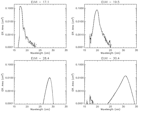
Figure 2-5. EUVI effective area. The solid lines are for the EUVI-A, the dashed lines for the EUVI-B.
CCDs were calibrated at the Brookhaven synchrotron and at the LMSAL XUV calibration facility. The entrance and focal plane filters were also calibrated at the LMSAL XUV calibration facility. The results of those measurements were used to fit CCD and filter response models. The calibration curves of the individual components were combined to obtain the EUVI effective area as a function of wavelength. The results are shown in Figure 2-5. The two telescopes (EUVI-A and EUVI-B) have very similar responses.
Using the calibration results we predict the response of the EUVI to typical solar plasmas. We take typical differential emission measure distributions (DEMs) reported in the literature, predict the resulting solar spectral line emission using the CHIANTI8 software, and combine the result with our calibration data. Table 2-4 summarizes the pixel count rates for selected solar features in the different EUVI channels. Note that CHIANTI underestimates the He II flux by typically a factor of three so we have multiplied the prediction by a factor of 3. Figure 2-6 shows count rates predicted for isothermal plasmas as a function of plasma temperature.
Table 2-4. Photon count rates (phot/pixel/second) for some solar features predicted with the Chianti code. The numbers for the 30.4 nm channel have been tripled to adjust for the fact that Chianti typically underestimates the He II flux. The first number in each box is for the EUVI-A, the second for the EUVI-B
| Photons/s/pixel | Quiet Sun | Active Region | M Class Flare |
| 17.1 nm | 92 / 98 | 954 / 976 | 25700 / 26700 |
| 19.5 nm | 40 / 41 | 784 / 792 | 92200 / 101500 |
| 28.4 nm | 4 / 4 | 118 / 130 | 5540 / 6110 |
| 30.4 nm | 30 / 30 | 428 / 419 | 18100 / 17800 |
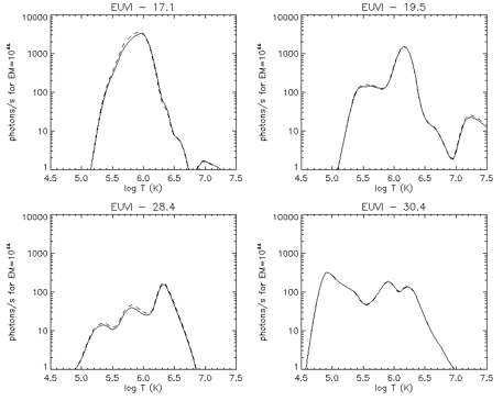
Figure 2-6. The response of the EUVI as a function of solar plasma temperature. The solid lines are for the EUVI-A, the dashed lines for the EUVI-B.